EVERYDAY OBJECTS · ORIGINAL 3D STUDY
How does one tiny slider join two rows of teeth?
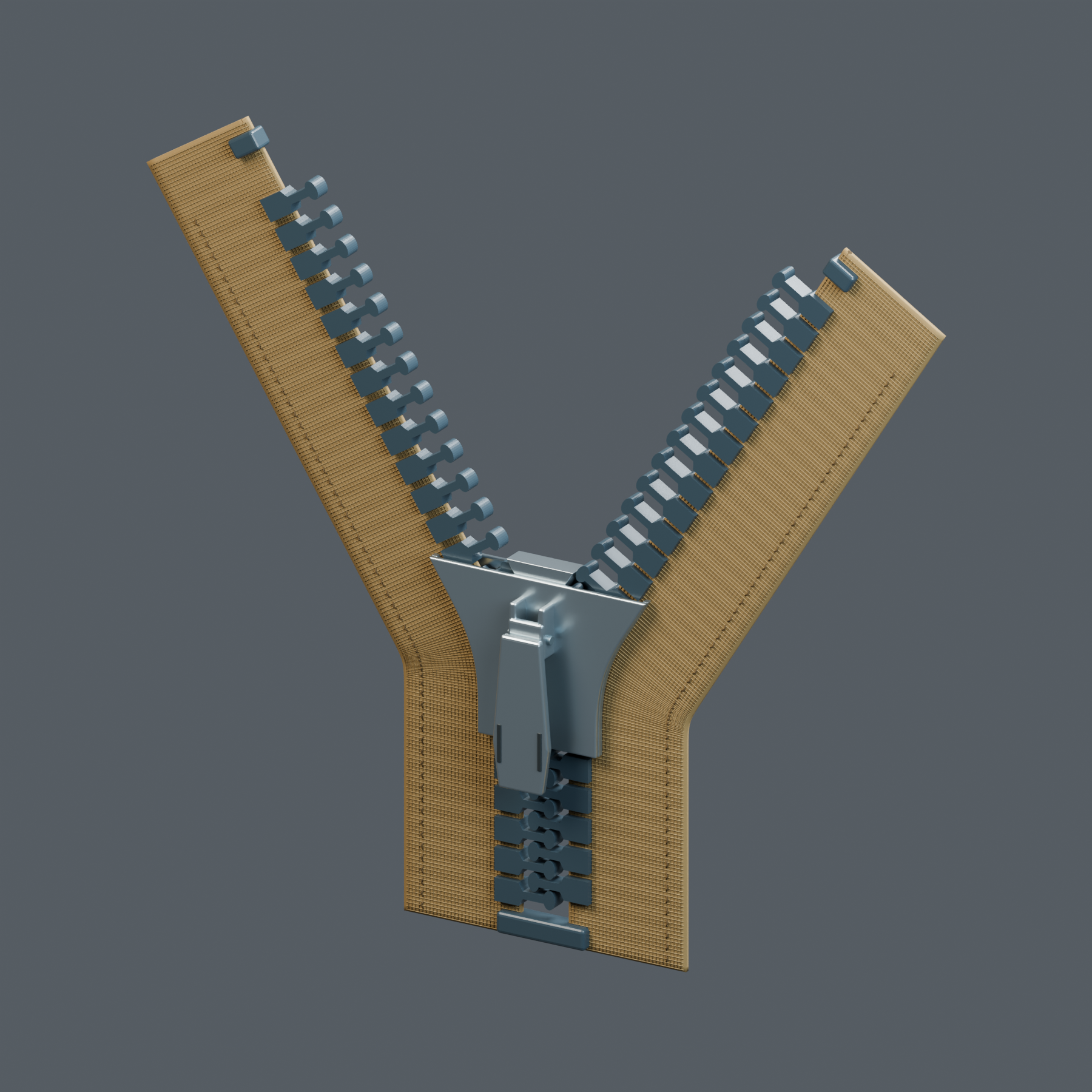
One slider guides two rows into a single chain.
Start with the narrated walkthrough.
See the whole mechanism, then inspect it yourself below.
Take it apart and inspect every system.
Click a part to highlight it and read why it matters.
A familiar object. A hidden system.
One slider guides two rows into a single chain.
A tiny Y-shaped passage does the organising.
The slider guides the two rows into an interlocking chain. Here you can lift its teaching sections and inspect the broad heads and narrow necks. This model preserves a static operating pose; its explosion is animated, while flexible tape motion is outside its scope.
The slider guides the rows. The tooth shapes make the interlock.
Read the explanation
Two lanes become one.The central neck divides the open side of the slider. Its outer flanges guide each row around that neck and into the merged outlet. The upper wing is hidden as a teaching section, not because it is a removable service cover.
Broad heads fit between narrow necks.These original moulded elements have a real coupling shape. Alternating heads nest between the opposite row’s necks. They are not magnets and are not created or melted by the slider. Shape and alignment matter.
The textile carries each row.Every element stays on its own tape. The textile can bend to feed the two slider lanes; the teeth keep their shapes. This teaching model holds that curved pose rather than depicting cloth as a rigid piece.
Stops keep the slider on the segment.The upper stops belong to their own tapes. A closed lower stop joins the bottom of this generic segment. It is not the separating box-and-pin construction used on many jacket zippers, and no automatic pull-tab lock is shown.
Sources and safety
- YKK Corporation: A conventional zipper combines interlocking elements, a slider and textile tapes.
- YKK Corporation: A Y-shaped passage in the slider guides two rows together or apart as the slider moves.
- YKK Corporation: The shape and dimensional fit of the elements and slider affect whether the rows engage properly.
Educational visualization, not a repair, safety-load or garment-design guide. The spatial explosion is an explanation, not a recommended disassembly sequence.
Scope and limitations
Original generic closed-end moulded-tooth zipper. Coil and metal constructions, automatic locks, repair, manufacturing tolerances and load or waterproof ratings are outside scope.
- Original generic closed-end moulded-tooth zipper: one consistent head/neck construction, not a metal/coil hybrid or copied product CAD.
- The rigid slider includes real upper/lower wings, side lips with textile slots and a central neck forming two entry lanes and one merged outlet. Slider subdivisions are teaching sections of a die-cast body, not a repair/disassembly instruction.
- This teaching model shows a fixed curved operating pose plus a fluid parts explosion; flexible cloth and contact forces are outside its scope.
A conventional zipper combines interlocking elements, a slider and textile tapes.Applies to: Original generic closed-end moulded-tooth zipper. Coil and metal constructions, automatic locks, repair, manufacturing tolerances and load or waterproof ratings are outside scope. Uncertainty: End-stop and separating constructions vary. This model is a closed-end example.
A Y-shaped passage in the slider guides two rows together or apart as the slider moves.Applies to: Original generic closed-end moulded-tooth zipper. Coil and metal constructions, automatic locks, repair, manufacturing tolerances and load or waterproof ratings are outside scope. Uncertainty: The static teaching pose does not demonstrate moving textile.
The shape and dimensional fit of the elements and slider affect whether the rows engage properly.Applies to: Original generic closed-end moulded-tooth zipper. Coil and metal constructions, automatic locks, repair, manufacturing tolerances and load or waterproof ratings are outside scope. Uncertainty: This is an original illustrative geometry, not a certified manufacturing drawing or strength test.